
There is nothing quite like good tube rectification. It gives the amp that extra bit of organic life with a more natural, open presentation, avoiding some of the harshness of SS rectification while bringing in the glory and beauty of sag and compression, something that SS fails to duplicate. Unfortunately, it seems the tube rectifiers of late do not quite equal the best of the NOS brigade in robust build and reliability. Attention to wiring detail in the PS is critical now more than ever, especially in more hearty circuits.
We have come upon a simple mod that helps reduce stress on the rectifier on start-up, especially when employing the stand-by circuitry. This startup surge is what seems to be causing issues with the latest run of valves as they can have a tendency to ARC and take out the mains fuse and sometimes kill the rectifier.
Rule #1, before working on the amp, make sure power is OFF. If it has a standby switch leave it in the on position and just cut off the power. Unplug the amp from the wall. Tube amps contain lethal voltages. Indeed, it is possible that even after the amp is unplugged high voltage can remain. If you are not familiar on how to discharge capacitors you should find a technician who can help you.
The process outlined below is a simple one in which we move the first filter
cap from the cold side of the switch to the hot side lug. After this mod,
when the amp is flipped to the "on" position, it slowly charges
the first cap. After the stand-by "Launch" switch is engaged,
the first filter cap essentially charges the rest of the filter caps thereby
taking the strain off the rectifier.
TOOLS NEEDED:• Quality Soldering Iron ie Weller
• Solder of Choice
• Good Needle Nose Pliers
• Solder Sucker or Wick
• Wire Cutter & Stripper
• 14mm Socket
Follow the instructions and you should not have any problems. After
rear panel removal, when removing amp from cab, undo reverb wires, noting
orientation. Amp attached from bottom. We usually remove all tubes,
also noting orientation.
**NOTE: Remember to use proper soldering technique here, avoiding COLD
solder joints, the bane of any build. If unsure or weak in this area,
it's best to have a tech or us do this work.
All photos below click to FULL SIZE versions for even more detail.
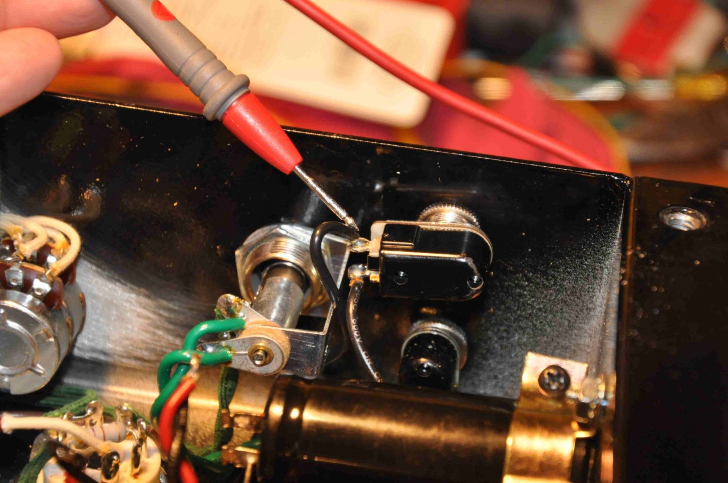
1) Unsolder the three wires that connect to the top of the first filter cap
this is the cap closest to the power and Launch switch.

See wires after unsoldering

2) Use a 14mm socket to loosen the launch switch from outside; rotate clockwise to access the solder lug. Unsolder the black wire going to the lug and remove wire to use later.
Use a solder wick or solder sucker to clean out solder in lug

3) Unravel the red and black wire so it is long enough to reach the lug you just unsoldered. You might need to clip the plastic tie in order to make it long enough.

4) Solder the Red and black wire to the rotated switch.
Note: You can re-twist wires here for more even appearance,
allowing room to make switch and rotate in next step.
5) Rotate launch switch counter clockwise to the other
lug.
And unsolder the black wire from the lug.

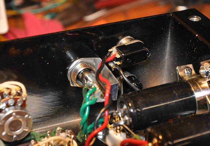
6) Move black wire that you just unsoldered from the switch and insert it into the lug of the first cap. Also take the black wire that you removed earlier and insert in the same hole of the first cap and solder everything together.

Two Black Wires now soldered to lug in first cap

7) Take the loose end of the black wire that was soldered to the first cap and solder it to the launch switch cut and strip wire to have a small amount of slack.

8) Check that the two joints on the switch are not shorting out once you have confirmed this rotate the launch switch to the original position and tighten down.

You have now completed the mod check to make sure that the wires are routed nicely. If tubes were removed, re-install in proper order, and test by hooking the amp to a speaker and turn on the power, letting it warm up for about one minute. After observing minute, flip the launch switch while keeping a eye on the rectifier to make sure it does not arc or exhibit anything abnormal.
Play the amp and make sure all is good, this before you install in cab.
Re-install amp into cabinet.
If you have ANY problems at all, or any questions, feel free to email or call Michael at 910.620.2512. As stated earlier, if you feel uncomfortable with this mod, it's best to have a tech or us do it.
Let us know how it worked out. Good luck!
MS & kh